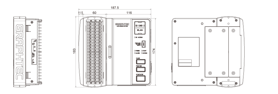
Monitorless Data Logger GLT400
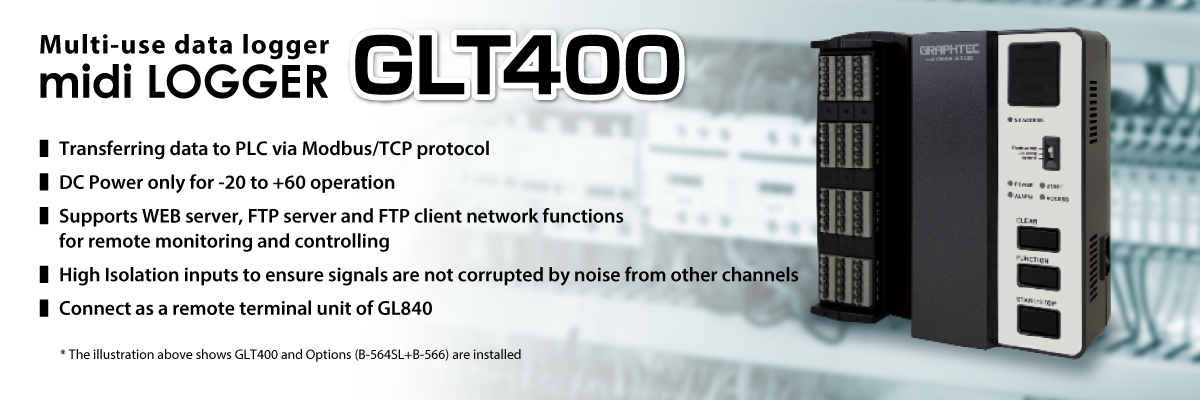
Multi-use & Multi-function Input Data Logger
GLT400 is a multi-use data logger that can be used as a extension unit and a stand-alone measurement such as utilization at research and development, newly expanding the sector to production engineering and production, incorporation into control panels and devices, data acquisition from PLCs via Modbus/TCP, and as PC loggers.
Three types of analog input terminals are available in the lineup, which can be selected due to the input type, and can be expanded from the standard 20 channels to a maximum of 200 channels.
We can provide a document on how to connect to PLCs and other devices using Modbus/TCP.
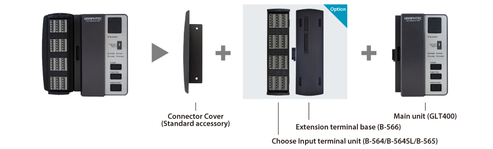
Expandable and Various Input Terminals Depending on Applications
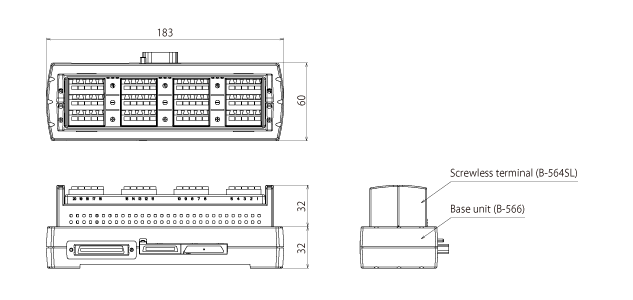
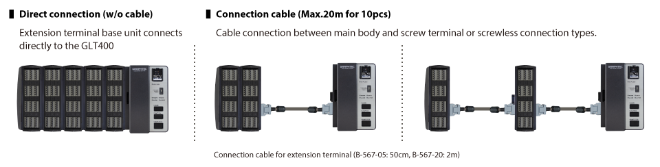
Combinations of input terminal / terminal base can make suitable machine configurations depending on measurement conditions.
Useful Functions of GLT400
Wireless LAN connection of
GL840 (main unit) and GLT400 (remote unit)
Can record standalone
- Mount or embed in a system
- Modbus/TCP for for PLC I/O channels
- Enable to use as PC hosted data logger
Connect as a remote terminal unit of GL840
- Wireless LAN connection
- Ethernet connection
- Wireless LAN & Ethernet connection
Analog Input Terminal Capable of Multi-input (common analog input terminal)
Voltage, temperature, and humidity can be selected for each input channel.
Use EU scaling for other measurement parameters.
Measure voltage
Supports wide operating range (from 20 mV to 100 V)
Measure temperature
- Thermocouple:K, J, E, T, R, S, B, N, C (WRe5-26)
- RTD: Pt100, JPt100,Pt1000 (IEC751)
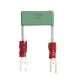
Measure current (4 -20 mA)
Shunt resistor (250Ω) is available as an option.
Equipped with a dedicated 1-5V range for the measurement range
- Shunt resistance 250Ω (B-551)
Cannot use B-551 resistor with B-564SL input terminal
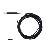
Measure humidity
A humidity sensor is available as an option.
Power for the sensor is also supplied from the main unit.
Equipped with a dedicated humidity range
- Humidity sensor (B-530)
Digital I/O port available
Digital I / O can be used by connecting an optional I / O cable.
- Input/Output cable (B-513)
- When connected as a remote terminal unit of GL840, this function cannot be used.
Logic/Pulse inputs (4 channels)
Logic : No-voltage contact (A contact, B contact, NO, NC) ,Open collector, Voltage input (H.L decision)
Pulse : 3 types of selections (Rotation / Quantity count / Instantaneous) per channel
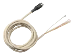
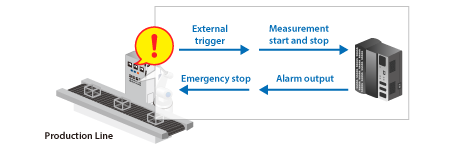
Alarm output (4Channels) & Signal input for external trigger (1Channel)
Start/Stop recording with external trigger.
Alarm output port (1 to 4) are set for each analog input channel.
Expandable Up to 200 Channels
By adding an analog input terminal and an terminal base, it can be expanded in 20ch increments from a min of 20ch to a max of 200ch.
| Channel Expansion (Sample) | 20ch | 40ch | 100ch | 200ch |
|---|---|---|---|---|
| GLT400 main unit | 1 | 1 | 1 | 1 |
| Terminal base | 1 | 2 | 5 | 10 |
| Input terminal (*) | 1 | 2 | 5 | 10 |
- Input terminal price is means of standard terminal price.
Terminals (B-564,B-564SL,B-565) can be mixed. However, if you mix B-565 with B-564 or B-564-SL, the specification of B-565 will be equivalent as B-564 or B-564-SL.
When connected as a remote unit of the GL840 series, 180ch is the maximum. (GL840: 20ch + GLT400: 180ch) (sytem max. 200ch)
Expansion method (2 types)
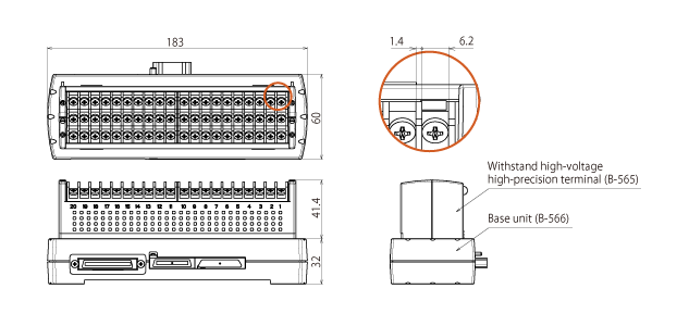
Various Terminals for Different Applications
- Standard terminal (B-564)
- Withstand high-voltage high-precision terminal (B-565)
- Screwless terminal (B-564SL)
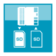
The Measurement Data is Safely Stored in the Flash Memory
Standard 8GB built-in flash memory and SD card slot.
- Internal memory: 8GB
- SD card slot: Support SDHC and Max 32 GB
- SD card cannot be used when the wireless LAN unit is used.
- Max single file size is 2GB. (use Relay mode to extend recording)
Support Long Term Data Recording
Number of channels and sampling interval
| Sampling interval | 10ms | 20ms | 50ms | 100ms | 200ms | 500ms | 1s | 2s | |
|---|---|---|---|---|---|---|---|---|---|
| Number of Channels | 1 | 2 | 5 | 10 | 20 | 50 | 100 | 200 | |
| Measurement target | Voltage | Y | Y | Y | Y | Y | Y | Y | Y |
| Temperature | Y | Y | Y | Y | Y | ||||
Sampling Interval and Capturing time
When all 20 analog channels are being used, File size of captured data is 2GB.
| Sampling interval | 10ms | 50ms | 100ms | 200ms | 500ms | 1s | 10s |
|---|---|---|---|---|---|---|---|
| GBD Format (Graphtec Binary Data) | 31 days | 77 days | 95 days | 108 days | 270 days | Over 365 | Over 365 |
| CSV Format | 3 days | 11 days | 16 days | 21 days | 54 days | 109 days | Over 365 |
Convenient Data Recording Functions
Ring capture function

The old data is deleted, and most recent data is saved. When stop the recording, selected data point is saved.
(Number of capturing data is 1000 to 2000000 points)
Relay capture function
Save data to multiple files with specified capturing time or file size until recording data is stopped.
Hot-swapping the SD memory card
SD card can be replaced during data capture when the sampling interval is 100ms or slower.
- SD card cannot be used in the slot while the wireless LAN unit (B-568) is used.
USB drive mode

Connect the GLT400 to PC with a USB cable and boot in USB drive mode, it will be recognized as an external drive for your PC. The measurement data in GLT400 can be transferred to PC by drag and drop.
Back up recording data
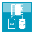
The recorded data can be automatically backed up to other storage media at regular intervals. FTP backup has a function to delete files in the main unit when the backup is successful.
Backup interval: 1, 2, 6, 12, 24 hour(s)
Backup file destination: Built-In Flash memory, SD memory card, FTP server
Data file format: GBD (binary) or CSV (text)
- Available sampling speed is 100 ms or slower when recording in CSV format.
- When the RING mode or external pulse synchronization sampling is selected for recording, the backup function is not available.
- The storage device specified as the recording destination of the measurement data can not be set as the transfer destination of the backup file.
- When backup is enabled and data file format is specified with CSV format, SD memory card exchange (hot-swapping) and RELAY recording are not available.
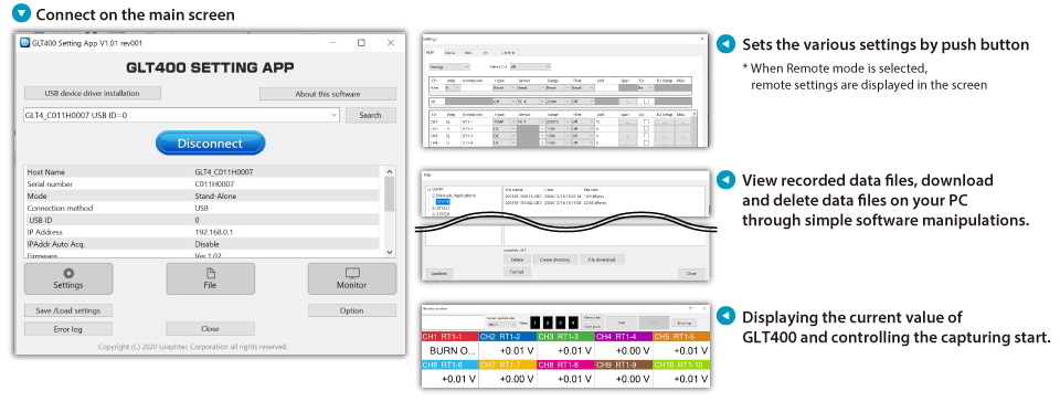
Standard Accessory for 2 Types of PC Software and Web Browser Function
Simple Operation Software “GLT400 SETTING APP”
Easily enter settings and monitor measured data from a PC. GLT400 is ideal for use with single unit. GLT400 inherited the setting screen menus from GL series.
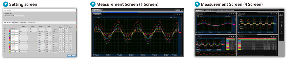
Advanced Function Software “GL-Connection“
Max 20 units of GLT400 can be connected.
Display modes come standard with a Y-T View, Digital View, XY View and FFT View.
Contains direct Excel functions and a file connection function. Can convert GBD files to CSV format.
Settings, control, data confirmation/transfer are possible from a PC without using dedicated software
- WEB browser function
- FTP client function